Piled raft
ELPLA is a powerful tool for analyzing piled-raft foundations. Today, nearly every engineering office has its own computer programs for the analysis and design of piled rafts. Furthermore, most of the available programs under Windows are user-friendly and give very excellent output graphics with colors. Consequently, theoretically a secretary not an engineer can use them. But the problem here is how can man control the data and check the results.

Many practical problems are available which are analyzed in detail by using the program ELPLA. It is important for the engineer to be familiar with this information when carrying out a computer analysis of piled rafts. An understanding of these concepts will be of great benefit in carrying out the computer analysis, resolving difficulties, and judging the acceptability of the results. Three familiar types of subsoil models (standard models) for piled raft analyses are considered. The models are the Simple Assumption Model, Winkler’s Model, and Continuum Model. In the analysis, rafts are treated as elastic or rigid. The Finite Element Method was used to analyze the raft, in which plate bending elements represent the raft according to the two-dimensional nature of the foundation.

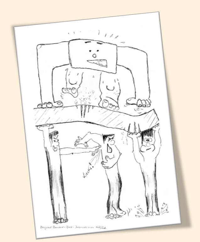
Figure 27 Pile-raft-soil interactions
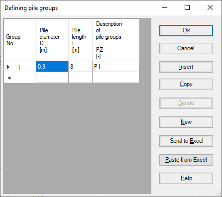
The simple assumption model does not consider the interaction between the foundation and the soil. The model assumes a linear distribution of contact pressures beneath the foundation.

Figure 28 Defining pile groups for Simple Assumption Model
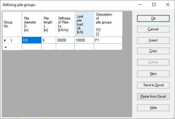
Winkler's model is the oldest and simplest one that considers the interaction between the foundation and the soil. The model represents the soil or piles as elastic springs. It is available in the two methods of Constant and Variable Modulus of Subgrade Reaction (methods 2 and 3).

Figure 29 Defining pile groups for Winkler’s Model
The continuum model is the complicated one. The model considers also the interaction between all foundation elements and soil. It represents the soil as a layered continuum medium or isotropic elastic half-space soil medium.
Although the Continuum model provides a better physical representation of the supporting soil, it has remained unfamiliar, because of its mathematical difficulties where an application of this model requires extensive calculations. Practical application for this model is only possible if a computer program or appropriate tables or charts are available. These tables and charts are limited to certain problems.
A general computerized mathematical solution based on Finite elements-method was developed to represent an analysis for pile foundations on the real subsoil model. The solution can analyze foundations of any shape considering holes within the foundation and the interaction of external foundations.
1- Nonlinear analysis using hyperbolic function Model
In this model, all forces acting on the raft will be transmitted nonlinearly on the piles using the hyperbolic function for Load-settlement.

Figure 30 "Defining pile groups" Nonlinear analysis using the hyperbolic function for load-settlement
2- Nonlinear analysis using German standard DIN-4014
In this model, all forces acting on the raft will be transmitted nonlinearly on the piles using German standard DIN-4014.

Figure 31 "Defining pile groups" Nonlinear analysis using German standard DIN-4014
3- Nonlinear analysis using German recommendations EA-Piles
In this model, all forces acting on the raft will be transmitted nonlinearly on the piles using German recommendations EA-Piles.

Figure 32 "Defining pile groups" Nonlinear analysis using German recommendations EA-Piles
4- Nonlinear analysis using a given load-settlement curve
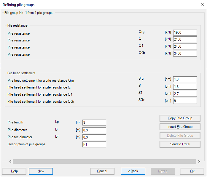
In this model, all forces acting on the raft will be transmitted nonlinearly on the piles using a specified Load-settlement curve. The load-settlement curve for pile group and piled raft can be obtained from two resistance-settlement relations as follows:
- Skin resistance with tip resistance-settlement, Figure 34.
- Pile resistance –settlement, Figure 35.

Figure 33 "Defining pile groups" Nonlinear analysis using a given load-settlement curve

Figure 34 "Defining pile groups" Skin resistance with tip resistance-settlement

Figure 35 "Defining pile groups" Pile resistance -settlement


